Research Pendulum - p9vh, fused quartz
In early April 2013 I (rlb) obtained 3 4 foot lengths of fused quartz tubing from GM Associates, Inc in Oakland, CA to use as the rod in my research clock. This test is designated p9vh. Fused Quartz is used because it has a very low coefficient of linear expansion cle.
Commonly cle is taken as 5.5 x 10⁻⁷ per degee C. This means that the rod which is cut to 829.35mm will expand or contract by that factor for each degree C around 20C. A very small number.
On April 13, 2013, Susan Grabau a designer and fabricator who works in glass helped me cut and drill one of the tubes to mount the tube in my experimental apparatus.
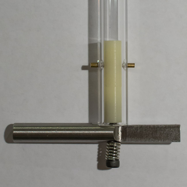
Below is an enlarged photo of the lower end of the tube which connects to a steel armature that fits into an electromagnetic drive solenoid to keep the pendulum in motion. On the right the 1/4 inch rod is shaped to slide without touching through two infared sensors which, in conjunction with a small computer, control the swing to within a few microns to eliminated any variation in circular error. For scale the tube is 10mm OD and 6mm ID. A 1 inch Delrin cylinder is held in place with a short bronze pin made from welding rod. The Delrin is tapped to receive a 4-40 machine screw. This spring keeps everything snug and allows the rotation of the armature to align with the solenoid and sense units. Note how the armature rests on the bottom of the quartz not the Delrin. This way the tube sets the length.
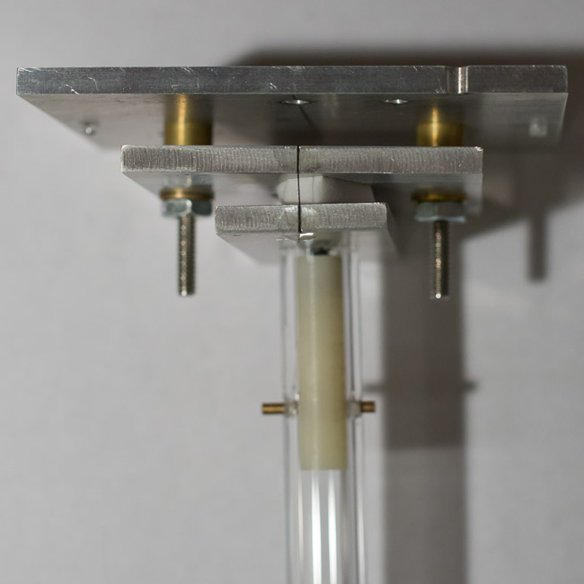
The next two photographs show the top of the rod with the gimbaled platform and flexure which is made of two silk threads one at the front and the other (unseen here) at the back. The focus of the first photo show the fixture clearly to be much like the bottom with a 1 inch Delrin rod tapped to 6-32 for the connection. Also seen on the top plate is a tiny saphire bearing to allow the whole pendulum to move forward and back in the housing to balance the load exactly on the two silk strands.
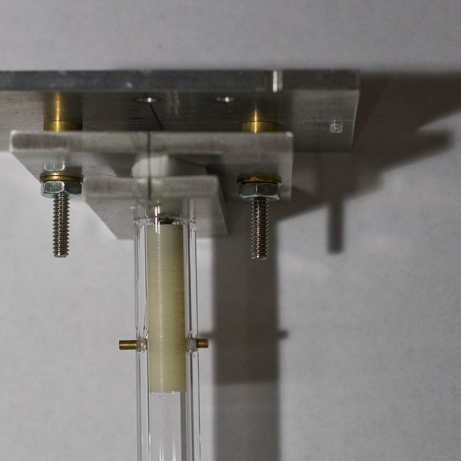
Shifting focus to the silk shows the fiber and the epoxy used to hold it in place.
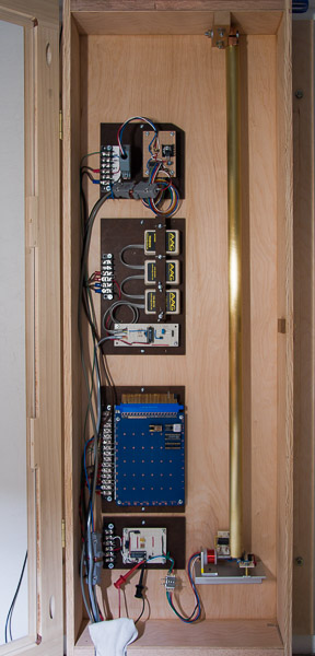 Shown here is the cabinet with an earlier experiment
using a 7/8 inch diameter brass rod and a beryllium copper
flexure. (p8)
The electronics modules on the left are from top to bottom:
GPS interface.
Environmental sensors for temperature, barometric pressure, and relative humidity.
Two channel interval timer.
Driver computer.
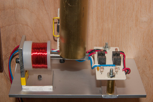
The photograph below shows in detail the drive/sense platform. The same armature is used in p9. The flexure at the top has been completely replace with the unit above plus some extra fixtures to complete the gimbale.
A laptop computer collects data from the device for every cycle of the pendulum. Data includes several temperature sensors, a barometric pressure sensor, a relative humidity sensor, the length of the GPS second using the timer module to eliminate various temperature variations in timings, the length of each pendulum cycle, the amount of drive applied to hold displacement constant, and a measure of the total angle traced.
This data is processed through a program of my own to remove short term noise from the measurement process, earthquakes, and mechanical noise from the house and street. (I once recorded the delivery of architectural stones across the street as they were dropped from the truck.)
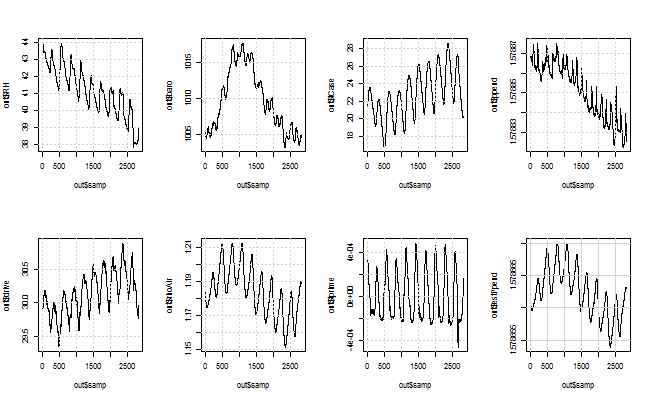
Next the condensed data is analysed using R from the RStudio frontend. The plot below was produced by R/RStudio. It shows all the performace details for over 9 days. The plots are top row first left to right: RH, barometer, temperature, period of the pendulum in seconds referenced to atomic clocks via the GPS, drive per cycle (about 60ms applied at center of swing), density of air, first derivitive of case temperature, and modeled period. The test started at timecode 20130414.213628 which is 2013/04/14 21H 36M 28S UTC and each point is 5 minutes after that time. (UTC is about what used to be called GMT or Greenwich Mean Time (sort of for real time geeks))
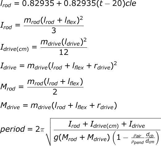
Below are the equations used to model this pendulum. These are converted from LaTeX to a .png image by this site. Instructions for making the format is here. Original LaTeX is here. (1KB) Here 'm's are masses in grams, 'l's are lengths in meters, 'r' is the radius of the drive/sense armature in meters, 'I's are moments of inertia, 'M's are moments, 'g' is the gravitational acceleration (about 9.8m/s^2), the 'rho's are the density of air or pendulum in kg/m^3, and the 'd's are distances from the point of rotation to the center of mass (cm) and the center of buoyancy (cb) in meters. For now this ratio is taken to be 1. The flex is taken to be 6.35mm, r to be 3.18mm, rod length 829.35mm, mass of the rod 91.2g and each Delrin fixture as 1.1g. Mass of the drive/sense armature is 11.6g with the screw and spring. Drive/sense length is about 54.4mm.
To match the observed period 'g' is slightly adjusted. Pendulum density is about 2343 kg/m^3 but that is in doubt just now. The mass of the silk and the rocking platform are taken to be zero as they contribute little to the total moment of inertia. I of drive(cm) is also very small as it is only the moment of inertia of a 2 inch 1/4 rod rotating about its center.
Temperature (C), barometric pressure (mbar), and relative humidity (%) are used to compute the density of air.
Discussion:
Every time I start a new pendulum experiment nothing goes as planned. This I will declare as the first law of horology - no clock behaves as expected.
One observation I've made over a couple of decades now is
that at first pendulums seem to speed up for a month or
so as they settle in.
Given that gravity is pulling on everything it would seem
that they should slow down - longer rod slower period.
But that doesn't happen.
It is if they schrink.
I don't know why this is, it is a
mystery for the future.
Anyway this one seems to be no exception.
Before the Enlightment this would have been just God's
will.
Now, I just don't know. Which either makes me a
scientist or a Bhuddist. Some 'ist' anyway.
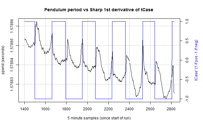
Now time is needed to gather much more data. (rlb)

